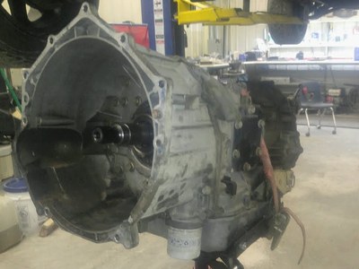
Allison 1000 Transmission Diagrams (Parts, Solenoid, Wiring)
While diagrams are very helpful, sometimes they are drawn in such a way they are hard to follow and understand. But when you are doing a DIY repair, diagrams are your best tool and guide.
Throughout this article, we will be displaying different diagrams for different areas of the Allison 1000 transmission. We would suggest that you print them out so that you have them handy when the time comes for repairs. Keep a separate folder for your diagrams to make it easier to find them.
To see these diagrams and some helpful information, just continue to read our article. It provides more diagrams than words this time so you have the best help possible when working on this transmission.
Finding an Allison 1000 Transmission Diagram
This is not going to be a tough search to make. Just type in the words Allison 1000 transmission diagram and you should have more than enough websites that bring you the diagrams and other helpful information.
The repair manual has the best diagrams but some of those images are not set up to be copied or pasted. The link to the repair manual that has all the best diagrams is here.
Just scroll down past the pay features and you will see a short list of manuals you can open for free. Just one click will get you all the information you want and if you can copy and paste or print will depend on the type of PDF feature you have on your computer.
Allison 1000 Shift Solenoid Diagram
The diagram for the shift solenoid is part of the diagram for the complete solenoid. The image has arrows with letters from A to F and those arrows point to the different shift solenoid parts as well as other key solenoid parts.

*** this is the allison shift solenoid but the diagram is not from the manual.
According to the manual, arrows C, D. & E are the shift portion of this part. You will find the diagram in the repair manual on page 17 and here is what the manual says about this function:
“Shift Solenoids C, D, E - Shift Solenoids C, D, & E are normally closed solenoids that provide the necessary logic to distribute fluid to the correct clutch packs in the transmission. The shift solenoids provide either full control line pressure, or exhaust, to the lands of each of the corresponding Shift Valves C, D, and E. Shift Solenoids C, D, and E may operate in the open or closed state with no modulation capability at all.”
Allison 1000 Valve Body Diagram
According to the manual, the solenoid is in the valve body. The valve body is what you see in the above diagram. Or at least part of the valve body is in the above diagram.
There have been 4 valve body designs and the image below will only show one of them. Here is the link to see images of all 4 designs along with a lot of instructions and information you should know about.

Allison 1000 Transmission Parts Diagram
This is going to be a lot easier to find as there are many exploding parts diagrams on the internet. The manual has some good diagrams of the transmission and individual parts.
Its exploding diagrams do not start till page 40 of the manual. In the mean time here is an image of the transmission with all of the parts labeled and separated for easier viewing:

*** Image taken from this website- https://transmissioncoolerguide.com/transmissions/allison-1000/allison-1000-transmission-parts-diagram/
It is hard to read those labels so we suggest that you download or print out the manual to see each part and its name. The manual does a great job of labeling everything very clearly.
Unfortunately, their diagrams go on for over 20 pages. It will take a little time to get to the specific area of the transmission you want to work on.
Allison 1000 TCM Wiring Diagram
There are some good images and diagrams for the wiring of the transmission on the internet. The following diagrams, and we will place more than one here so you get a better idea of what you are working with come from this website.
There are quite a few diagrams on that website for you to check out. Unfortunately, space is limited here so we can only do a couple of diagrams for your benefit.


That website has quite a few wiring diagrams and even one for the 4th generation Allison transmissions. It is a handy resource to have as it coversmore ground than we can today.
Allison 1000 Transmission External Wiring Harness Diagram
The diagram is found on page 8 of the repair manual:

What the manual says about this part is:
“The electronic control of the transmission is performed by the Transmission Control Module (TCM). Transmission Control Modules are available in both 12V and 24V configurations, to match the configuration of the vehicle's electrical system.
The TCM, shown in Figure 6, receives and processes signals from various switches and sensors. The TCM determines shift sequences, shift timing, and clutch apply and release pressures. The TCM uses this information to control solenoids and valves, supply system status, and provide diagnostic information for service technicians.”
There is more on page 9 of the manual about the different sensors involved with this wiring harness.
Some Final Words
These diagrams should give you a nice head start on your transmission repair. The best place to go for your information will be the repair manual we linked above.
This manual goes for 120 pages and has more diagrams than most other manuals seem to have. This makes working on your transmission a lot easier. As usual, if you are not a transmission person, it is best to leave the transmission repairs up to the professionals.
They will get the job done for you.

